2014. december 11.

An easy repair of a C64

Dirt and spilled capacitors
This Commdore 64C was in good condition for first sight, and worked besides some minor problems, like defective "0" key, and didn't have sound. Adding a spring from my donor C64 to the keyboard, for the missing "0" key was a 1 minute fix. However, opening up the case afterwards was surprising: this later C64C had a casing where there were no screws just plastic hooks to snap the keyboard in place, and snap the whole housing together. It seems to be a cheap solution, however was easy to open up for fixing.

Nice and clean, with new caps
Inspecting the motherboard, in general it was in good condition, however some spilling under two electrolytic capacitor grabbed my attention. Also, the fuse looked strange for me, it seemed to be home renewed: the hair thin burning wire run outside of the glass, and it was soldered to the fuses metal ends. WTF??

Soldered out the capacitors, and washed the main board to get rid of the remains of the fluid on it. Swapped the fuse from the donor, and soldered in the donor capacitors. Anyways, having the capacitors soldered out, I took the opportunity to measure it's properties. Turned out, that even the original capacitors were within specification, however the ESR values were 1.5, 2 times as high as the new ones.

Testing, testing...
Powering up the board, checked the voltages on SID, and I have found everything OK. The SID (the newer 8581 version) requires 0V (GND), +5V and +9 volt. I swapped with a known working one, for testing purposes. And let there be music, I said. And so, there was.

Hitech quick dry procedure
One thing left for the end, cleaning the bare casing thoroughly. All of those small black scratches, old dirt went away, and assembling together again when it dried out, we were ready to play a little bit. :)
Ready to have fun!

2014. december 8.

Repairing Commodore 1351 mouse

I have a Commodore 1351 mouse bought ages ago, for chips. It wasn't functioning properly, since the horizontal movement didn't work. It was sitting in the drawer, waiting to be repaired, until this week. Since I managed to copy GEOS to a spare floppy disk, with my new ZoomFloppy device, it was high time to use it. The symptoms are: it moves the cursor up and down properly, however no horizontal movements at all.

Opened up the casing of the mouse, I found it quite dirty, collected a lot of small particles everywhere around the sensing wheel as well, so my first move was to get rid of that oily dirt, and clean the casing too. The easiest way to clean the PCB, and grease, particles, is to use break cleaner spray used for cars. It dissolves every kind of oils, and sticky dirt, and sublimates very quickly leaving a clean surface afterwards. For the housing I used Domestos, an aggressive whitening cleaner could be easily obtained here around.

Small blue spots are the IR emitters
Cleaning wasn't enough though. I quickly checked the cable with multimeter resistance measurement, looking for incontinent, however I have found everything all right. My next move was to observe whether the infrared transmitters emit light or not. It is a little tricky, since you can not see IR light, however, digital cameras can... like the ones can be found on smart phones. You just need some darker places to see those small bright spots. As you can observe on the picture I took, those IR transmitters are visible as bright blue spots on the picture. You could also observe, that one of them (lower right hand corner) is emitting dimmer than the others. This could be a problem, since probably it's light is not enough to sense movement. Probably that particular LED is getting worn out, but still operational though.

Blue resistors are the new ones
Since I didn't have any spare parts to replace those, and didn't even seemed to be an easy run, I checked the device further. Putting to good use my oscilloscope again, measuring all of the IR receivers on the other side of the wheels, opposite to the IR transmitters, while I was rotating the wheel in front of them. As I measured, I realized that the ones associated to vertical movement, modulates the 5V power source between roughly 0V and 3.8-4.1V. However, the receiver on the X axis, opposite to the brighter emitter modulates between 0V-3V, and the one opposite to the dimmer emitter between 0V-1.8V. But at least, it was a sign, that the receivers are also in working condition.

Commodore 1351 connected to C=64
Traced back the PCB from the IR receivers, I concluded that it works the following way: they are sourced from the 5V power line, and connected to the IC with different kind of pull down resistors, to make the 0V when they don't see any IR light, and closer to 5V when they are. However, I was surprised, that every IR receivers had different pull down resistors in place, probably manufacture time compensation of small differences. The 4 resistors varied from 5.5kOhm to 12kOhm. I quickly need to add, that the two smallest resistors were connected to the X axis receivers. This means, that probably sometime they were capable to drive more current, either because the emitters were brighter, or the receivers degraded by time. So, my theory was: swapping the two small resistors for bigger ones, makes the receivers pull up the line more easily, which means higher amplitude oscillation compared to 0V-1.8V.

C=64 with 1351 mouse, running GEOS
At first I soldered out the two resistors, and added 9.9kOhm ones instead. Checked again on the oscilloscope, nice high amplitude produced by all receivers. Still in the taken apart state, I connected to the C=64, loaded up GEOS, and tested rotating with fingers the individual wheels: works perfectly! Nice job! Assembling together with it's house, I was eager to click around in GEOS... and came the disappointment: the X axis didn't work again. Taking it apart again, checking soldered connections again, everything is fine. Connecting the raw PCB to the C=64, it also works fine! Ok, probably it was some temporary thing, maybe a connection problem. Assembling together again, and testing: X axis doesn't work again. Hmm... probably the PCB, and the housing of the wheels + IR emitters and receivers bends, when I tight down with screws, and gets the two receivers out of alignment. I have loosen the lower screw, and TADA! Works! A little bit unreliable on the X axis sometimes, but at least it works. Now I know, it is a misalignment issue from now on (mechanical).  But at least it became usable. I have a working Commodore 1351 mouse finally!

2014. december 4.

Connecting Commodore floppy to Windows 8.1 laptop

CBMXfer, finished copying GEOS
Back at days, when I had last time a desktop PC at home (it was an AMD Athlon 2500+) in around 2000, it had a conventional parallel port. I was also able to boot it up in MSDOS 6.2, to make exclusive use of that mentioned parallel printer port to connect my Commodore 1541 floppy with StarCommander, and make file transfers back and forth. However, since than, I only had laptops, not having parallel or serial ports, but still wanted to connect my old floppy drives to PC somehow, to transfer those zillions of D64 images I collected from net, to test on actual hardware.

Laptop using Commodore 1571 drive
Now days, I need to say, the most comfortable way to command your Commodore IEC drives (Commodore 1540, 1541, 1570, 1571, 1581, etc...), is to get your hands on a ZoomFloppy device, also known as xum1541 cable. This is a micro controller based USB device, accompanied with drivers for Windows, and some command line utilities to do actual things with it. I also looked up the ebay to find some implementations, since I didn't want to bother making it myself.

I ended up buying 8_bit_fan's smaller implementation, not having IEEE-488 port. The product arrived without any software bundled with it, so I needed to look up, and download everything I needed to make it work. At least, it wasn't expensive. OpenCBM is compatible with this solution, however, the latest version didn't contain the support yet, so I needed to download a prepacked, xum1541 supporting OpenCBM verison, directly from ZoomFloppy's website. Installing the drivers wasn't smooth, since there is no official support for Windows 8.1. The problem is that the USB driver is not signed, so by default, Windows 8.1 won't allow you to install it. To workaround this problem, you can hit the restart while holding down the shift key, in the power drop down menu, on the start screen, to restart your computer in maintenance mode, and selecting the "Disable signed driver constraint" or similar by pressing F7, you can boot into an operating mode, where you can install the driver, even though it is not signed. Rebooting afterwards in normal mode/way, and you are done. Otherwise you just need to follow the steps in the manual you get.

I have found command line operation cumbersome, so I downloaded CBMXfer also. To make work properly, you'd better place it in the ZoomFloppy's version of OpenCBM bin directory, and run it from that location. To make it even more convenient, you should also download and install the latest VICE 6502 system emulator (C=64, C=128, PET, etc...), and copy c1541.exe from it's directory to the same directory where CBMXfer is.

This way I can access my Commodore 1541, 1570, 1571 drives with no hassle, and even brows files stored in the D64 disk images, brows the net, and display the screen of my C=64/128 simultaneously using AVerTV on my Windows 8.1 laptop. :)

2014. december 2.

S-Video cable for Commodore 64 & Commodore 128

Since I got rid of my TV half a year ago, I only use an AverMedia USB hybrid TV dongle for vintage computer video display. I experimented with UHF RF output, with minor success, and also converted one of my C=128 monitor cables to give composite picture. However, it wasn't satisfying enough, so I decided to make an S-Video cable, that can be also attached to my USB dongle.

What is the gain in it? One would ask. Well, let's dive into a little bit of the different video formats first, and how the Commodore 64 produces those. The Commodore 64's VIC chip outputs chroma and luminance signals separately. This is the source of everything displayed, in any format. The luminance signal is essentially an old school black and white signal, which even by the oldest B&W televisions can be decoded and displayed, provided they are working with the same 50Hz mains, since their timing is closely related to that frequency source. The chroma signal in the other hand, is a PAL encoded color information, appropriately synchronized with the luminance signal. After some amplifications, and line separator circuitry, those are available as output as well. However, the amplifier module also mixes the two signals together, producing composite output. This one also can be found as output on the Commodore 64. Mixing the composite signal again with the mono sound channel data, encoded into the picture frames, and putting all these things onto a UHF carrier frequency produces the PAL RF output, which can be tuned on a TV, around UHF channel 36.

AverTV C=64 S-Video screen capture
Since S-Video is essentially a separate chroma and luminance signal carrier plug, we can see, that we would be able to ignore all of the possible distortions added with mix-matching all other signals, to ultimately produce composite, or even worse, RF output.

Quickly looking up the net for a wiring diagram, for SCART cable (which also contains the S-Video signals too), and an S-Video mini-DIN plug pin arrangement, I was ready to solder things together. Since S-Video signal doesn't contain sound, I also needed to make a separate RCA connector for that, on the receiver side, next to the S-Video connector.

The first tests showed flickering colors, even flickering screen, in fact it looked even worse than it was on the composite. At first sight I was very disappointed, but after that I recalled that I red somewhere that the Commodore 64/128 chroma signal is too strong for modern TVs, for their S-Video connection, so somebody installed 330 Ohm resistor in the way of their chroma signal cable. Looked around, and only found 200 Ohm resistor at hand. Quickly modified the cable, added that resistor into the C=64 DIN connector housing, and TADA! Works! Great! Finely detailed, vibrating colors, crystal clear display! By the way, grounding the sound input pin on the video connector really makes a difference, by significantly lowering static whoom noise.

2014. november 25.

Commodore SR4148R restoration finished

Hello from Commodore :)
Last time, I have installed a temporary alkaline battery pack into the calculator, to try whether it works or not. After that, I looked up the internet, to collect information about the AC adapter. I have found that, the original could provide 6V 400mA DC, through a normal, mono 3.5mm jack plug, where the pinhead of the plug is the positive polarity.

I ordered a configurable AC adapter, with 1A output, and option to set voltage from 3V to 12V. Also got a 2000 mAh NiMH battery pack, which is a low self-discharge version, instead of the original 500 mAh NiCd pack. Since the original pack was designed to 50 mA charge for 16 hours, there is no charge termination circuitry implemented inside. Which is fine for a NiCd battery. Fortunately, there is not much difference between the charge profiles of NiMH and NiCd, however a bigger capacity battery would miss the C/10h constant charge (fe.: 800mAh/10h=80mA), never charging up the batteries. However a low self-discharge version of the battery will be satisfied by the lower current.

Swapping the packs, and turning the calculator on, everything was fine. Plugging in the adapter I could measure 60 mA charge flowing into the pack, just as I expected.

It seams, that the device is expecting the battery inside heavily as a mediator/regulator, since not having the battery inside, just plugging in the adapter didn't do anything usable, just random characters on the screen (probably too low voltage for operating, didn't debugged any further).

Quickly made some new pictures, and TADA! Ready to use... erhh... charge. :)

2014. november 15.

Commodore calculator SR4148R repair

Last week I managed to put my hands on a 1974 Commodore SR4148R calculator. It was said to be non working. Never the less, I was thinking that this one seems to be in very good visual condition, just a little bit dirty, and in worst case, it could be used as a spare part donor, whenever I manage to get an other one. There was unfortunately no leather case, nor AC adapter packed with it, and the operating manual was also missing.

Getting home, I quickly opened the case, and saw that the original 500 mAh, 3 cell NiCd battery pack was in very bad condition. Electrolyte was flown out of the batteries, and made a big mess all over, inside the casing.

My first move was to take it apart, into as small pieces as I could, and wash the casing, and display. I soldered out the battery pack, and unscrewed the jack plug to be able to remove the display from it's place, and unfold all of the electronics, which consist of two PCBs, where the button back panel is a double sided PCB, and the logic board is a single sided, through hole mounted one. Awesome! The display has a series of small lenses in front of the very small LED display, melted together.

As I took it apart, when unscrewing the back panel of the keyboard, I had the feeling getting stronger and stronger, that the keys would be something very unusual these days. When lifting off finally the panel, I saw the following: every key on the keyboard is a separate small piece of plastic, with rubber/carbon circuit touch contactors, and a small spring for every single button. It also seems, that the buttons are not just simply painted ones, but there must be some protecting layer above the paint, preventing the signs to wear off. All of these features add a very pleasant, and very distinct touch feeling of the buttons, even though they are small.

I have the feeling, that this calculator was designed for eternity. The buttons practically were never meant to wear off, the PCB is small, simple, through-hole type, and very easy to fix, in case something goes wrong. Since I didn't have any jack plugging adapters right at hand, I decided to quickly wire up a small temporary replacement battery pack, from AAA alkaline batteries, just to try whether the thing as operational at all. Turned on, nothing happened. Measured the electric flow, and it was 800mA when turned on, but no display. There must be some shorts, or disconnects.

As I suspected, I have found some disconnects, since the electrolyte during the years managed to make complete PCB track segments to disappear. I have created some jump routs out of wire, and TA-DA! It works! It's consumption is around 70 mA, when simply turned on. Put together everything, and started to joy-key on some expressions.

Testing it I started to like it more and more. There are three blue keys on the top, marked EE, EE *down*, EE *up*. I have never seen such thing before. Ok, the EE is quite self explaining the exponential enter button, however with the other two, one can modify the punctuation on the fly, converting even a calculation result into other exponential result. This also makes counting 10s, 1000s, millions, very easy! I have also discovered a bug! 2^31 is OK, However, 2^32 is 4294967297 according to the calc, instead of 4294967296. However, when I divide the result of 2^32 by 2, I will get the correct 2147483648.
Even more strange, when I type in 4294967297, and divide by 2, I will get the mathematically correct 2147483648.5 as the result. 2^33 is also problematic, it is also bigger by one then the correct answer. Strange. I also very much like the small, thin LED numbers, and the strange delay we are not used to these days, when hitting the equals sign. :) After all, it is a very attractive, good to handle small scientific calculator, which was made for eternity! :)

Update: testing further the x^y functionality, it seems that it is a rounding problem inside the calculation, since 2^3-8 yields 1.6E-10. This also means, that the internal floating point representation is more precise than 10 decimals. Since single precision floating point numbers (32bits) can represent only 2^23 precision, it is too small for that purpose. Double precision (64bits) however would be a waste. My guess is it uses some arbitrary floating point representation, like 1bit sign, 8bits exponent, and at least 35bits fraction, which gives at least 44bits all together. Strange.

2014. november 10.

How I rescued a Commodore 128

I have got a Commodore 128 for free, when buying some Polski Fiat 126 parts some times before. The C=128 was waiting in his ashes, to rise, since it couldn't be turned on, and got some other issues as well.

When I pulled it out last weekend from the storage, to take a closer look, I instantly realized that the main problem was the power switch. Took one of the spare part C=64 as well, and soldered out the switch and installed it on the C=128. Checked, connections are OK, power is OK. However, there was a small discontinuity on the ground connection for the power LED. Soldering done, and shines as before.

Checking luminance on VIC
Since I didn't have an analogue TV at hand, I used my laptop with AverMedia Hybrid USB TV, to capture the display of the machine. First, I connected it to the RF antenna slot, to try to tune in the C=128 boot up screen. I only got screen pictures for some prompt times, mainly static pictures buffered by the TV card. And it was all black & white. I tried to fine tune, without chance, also tried to fine tune the RF modulator on the Commodore. The best I could get with PAL settings, is a black & white picture scrolling upwards, with great flickers on every second row. Also connected the video output to the composite in of the TV card, with the result of somewhat nice picture... in black & white.

C=128 main board
I quickly opened up the troubleshooting guide (which is for NTSC versions anyways), and followed the steps to narrow down the problem. Fortunately I have an old analogue oscilloscope, with 20 MHz measurement frequency. I quickly checked the different clock lines on the motherboard, and measured their frequencies with a rough estimation, since there is no such things on this 'scope as freq counter. The pin 16 of the VIC chip gives the luminance encoding, and pin 17 the chroma. Both were OK, however, the chroma seemed somewhat low on amplitude.
Donor C=64
So either the chip, or the M1 (the RF modulator) was faulty. Anyways, it seemed unreasonable, that the VIC chip give good signal with bad amplitude, so I turned to the RF. The modulator also contains an amplifier for the luminance and chroma output for the video connector. I measured with 'scope, and got a pretty distorted, low level output on it. So, the problematic part should be the RF modulator's chroma amplifier.

C=128 & C=64 RF modulator
I quickly soldered out the modulator from the C=64 in under 2.5 hours (since practically it is the same as the C=128 has). The procedure was pretty frustrating, not having the right tools to do it. What I missed for this action, is some kind of an IC pin heater head for my soldering-iron, and a solder sucker pump. Anyways, in 4 hours, the "new" RF modulator was in place in the C=128. Check with the oscilloscope: higher amplitudes on VIC chip, less distorted and higher level chroma on the video connection.

When I connected to the TV card again, with composite, from time to time, colors appeared and disappeared, wasn't usable. On the forums I quickly searched through, somebody mentioned that the frequency of the PAL oscillator crystal is very important, and should be very accurate. I didn't have a chance to measure frequency as accurate as 8 digits on an analogue oscilloscope, unless the 'scope can do XY plot option, and have an accurate freq generator. I lacked the later one, so I went blind. Exchanged the xtal and the variable capacitor from the C=64, and fortunately enough, it did the trick!  :)


Now I have an (other, also) fully functional Commodore 128, in nice visual condition. Later, I will try to test it also in 80 column mode, when I have a chance.

Also, I have a newcomer, an even older, Commodore CBM 720 to be restored. But this will be an other story.

2014. október 26.

Folytatás

Az elmúlt időszakban semmi időt nem tudtam János felújítására fordítani. Az autó félkészen, de nagyobb darabokban hever a garázsban, sok apró tehendővel a készig. A hosszú hétvégét kihasználva, kerítettem magamnak 2 fél napot, hogy kicsit játszak tovább a felnőtt legóval.

A motort ugyebár a szerelőmtől működő képes állapotban kaptam vissza, az alábbi megszorítások mellett: a saját karbimmal nem indult, így egy kölcsön karbit kapott, diagnózis: valószínűleg a mágnesszelep a hibás, mert nem kattan. Az Abarth szelepfedelet nem sikerült neki a karbi miatt feltenni, mert nem fértek el egymás mellett, így egy hagyományos szelepfedelet kapott kölcsön. Ha kész az autó, akkor egy szelephézagállításra azért még menjek vissza hozzá.

Gondoltam, akkor ezek közül egy pár dolgot orvosolok, mielőtt tovább haladnék. Kölcsön karbi le, saját fel, tényleg nem indul. Saját karbi le, immel-ámmal megpucol, vissza, elindul, de durrog, karbiba visszalő a henger. Gújtás kábelek rendezget, tartalék karbival kipróbál, kicsit jobb, de hirtelen gázra nem reagál jól (lefullad). Kölcsön karbi fel, már el sem indul. Közben próbáltam a saját karbimban az új mágnesszelepet, de akkor nem volt alapjárat egyáltalán. A turpisság kiderült: a régi mágnesszelep tűje le van nyisszantva, így mindig nyitva van. A másik két karbiba pedig nem megy bele a mágnesszelep. Az újról pedig az derült ki, hogy teljesen más a fúvókájának az alakja, hossza. Ezzel még lesz dolgom, valószínűleg Lada mágnesszelepet vágtak hozzám a boltban. :(

Kicsi fórumozás, gondolkodás, és polski biblia olvasgatás után arra jutottam, hogy lesz ami lesz, szétszedem megint a saját karbimat, beállítom az úszót benne (ebből kapott újat), kiszedek minden kiszedhetőt, és átfújogatom féktisztítóval. Illetve nem haolgatom, beállítom a szelephézagokat is. Vasárnap, amíg meg nem érkezett Andrei, ezeket meg is cselekedtem. Aztán Andrei kiszúrta, hogy ez bizony gyújtás, azon belül is megszakító probléma. Így tanácsára azt is szétkaptam, megdörzsölgettem csiszoló papírral az érintkezőpogácsákat, illetve csináltam egy új kábelt onnan a trafóhoz, mivel az is elég gatya állapotban volt.

És láss csodát, beindul a kicsike. Vígan pöfékel, mint egy, a műtőasztalon, átültetésre váró szív duruzsolt a kerékgumira rakott falemezen, zötyögve, berregve. Az alapjárati keveréken állítottam, így már a hirtelen gázadásra is reagál. Közben valami történt a Lada olajgombával, mert folyton azzal riogatott, hogy nincs olajnyomás, így sebtében visszaszereltem a polski sajátját. Meg is nyugodtam, amint elaludt a lámpa.

Köszben az Elegant (Polski Fiat 126 650 EL) gyújtás részleteiben is elmerültem, Sás, FZRTom és Andrei a fiat126.hu fúrumon nyújtott segítségével megrajzoltam az elvi kapcsolási rajzát a cuccnak, illetve a fehér foltokra fényt derítettem. Egy kevés google translate segítségével a lengyel oldalakról pedig felszívtam a tudást, amit erről az elektronikus gyújtásról tudni lehet.

Vasárnap még gyorsan felpattintottam a saját karbi talpamat (amin van egy vákuumcső kivezetés), a saját karbimat (egyelőre még a kiherélt mágnesszeleppel), és az Abarth szelepfedelet. Kipróbálni, hogy jön-e belőle az olaj, illetve hogy nem szív-e fals levegőt, majd legközelebb fogom, ahogy az elegant gyújtást is legközelebb tesztelem, és írom le a tudnivalókat róla.

2014. szeptember 11.

Kicsit megtorpantam

Új rögzítőfül, csavarból
Az utóbbi időben kicsit alábbhagyott a fejlesztési munka Jánoson. Eleninte apróságokat fejeztem be, illetve vártam a váltóra, meg a motor elkészülttére. Időközben persze mindkettő befutott, egy igen sok időt elrabló csemetével együtt, így most ez utóbbinak bajlövésére (trouble shooting) fókuszálok.

Amíg vártam a váltóra, és a motorra, és még a kisded a pocakban volt, addig még gyorsan összeraktam a műszerfalat. Egy bontott külső borítást szereztem még annó, ami nem annyira deformált, mint az enyém volt. Ennek amúgy megvolt ugyanaz a hibája, nevezetesen a felső rögzítőfülei le voltak törve. Ezt egy fúrással, illetve egy nagyfejű csavar becsavarásával pótoltam. Hogy a megfelelő felfogatónyílásba beférjen, kicsit le kellett a csavar fejéből az egyik oldalon köszörülni. Beszerelés után, most atom stabilan feszül a helyén.

Innen már tényleg csak a motor hiányzik
Aztán bekötöttem végre a benzintankot is, anélkül hogy nagyon kiszereltem volna (a beöntő csövek rajta voltak még). Ez elég nőgyógyász megoldásnak tűnt, így egy kevés szöszmötöléssel bizony járt a dolog. Mostmár minden a helyén van, innen már tényleg csak a váltó-motor páros hiányzik csak. A biztonság kedvéért, a benzincsövet jó hosszúra hagytam, amit majd beépítés után fogok méretre vágni.


A bajuszkapcsolóm elgé öregecskének látszott, ezért úgy döntöttem, hogy lefestem azt is feketére. A piktogrammokat rajta persze kitakartam előtte. Egy kis csiszolás után a fekete matt festéktől ismét újszerű állapotban pompázik, és azok a napszívta, kiszürkült foltok is eltűntek róla, amik az autó összbenyomását rombolták volna. Sztem szép lett.

Holdjáró abroncsok, festés előtt
Amikor annakidején lakatolsára átadtam az autót, akkor már a lehomokszórt, általam lefestett felniken állt/gurult az autó. Ezek a kerekek voltak bent, amikor az alvázvédőt is megkapta, illetve a festéket is felhordták rá. Így volt rajta idegen anyag rendesen, ami önmagában is újrafestésért kiálltott. Viszont hozzátartozik az igazsághoz, hogy azt még az első alkatrészek között fújtam le, és még nem volt gyakorlatom ebben a műfajban. Azóta sokat fejlődtem, és most már tudok foltmenteset fújni. A problémát az okozta csak, hogy most a gumik rajta voltak, így ki kellett őket maszkolni.
Ezt a gumi leeresztésével, csavarhúzóval eltávolítva kicsit a felnitől, papírdarabokat tömködve a felni és a gumi közé oldottam meg. A gumi ismételt felfújásával szépen odaszorította a papírt a felnihez. Ez igen pepecs munka volt, de a 40 perces maszkolást sikerült a negyedik guminál már 15 percre lenyomni.

Az autó belsőterével is foglalkoztam egy kicsit. A műszerfal után, a kormányoszlop összeszerelése következett, a "felújított" bajuszkapcsolóval. A dudáról kiderült, hogy visszaszerelve nem szól. Kiszereltem hát, hogy megvizsgáljam. Kiderült, hogy a csatlakozóvégek voltak kicsit rossz állapotban, illetve a duda hátulján lévő csavarral a rezgési hézagon kellett kicsit állítani, hogy megint minden rendben legyen. A váltóalagút kárpitját leszedtem, ez végül nem lesz tartozéka az autónak, és a tervezett helyre, a fűtésalagút tetejére felfúrtam, és rögzítettem a poroltót. Csak hogy kicsit sportosabban nézzen ki. :)

Aztán egyszercsak megérkezett a váltóm! Nagy Köszi Sankotuningnak! Belekerült az ötödik fokozat, illetve új féltengelyek, szimeringek, tömítések. És különben is... ránézésre is sokkal gusztább lett! :) Szépen beleöntöttem az olajat, és mivel tudtam, hogy beépítés előtt üresbe kell tennem, hogy a rugalmas összekötőt megfelelően be tudjam majd faragni, nekiálltam. Nem is gondoltam volna, hogy azt a kis kart rángatva ez ilyen nehéz lesz. Végül az oldalán található golyós pozícionálót kicsit kicsavartam, hogy könnyebb dolgom legyen, így már sikerült.

És akkor nagyjából itt meg is állt a project, egy kis időre. A motor még megérkezett, azt külön beindítottuk, működik most szépen. A képeken már viszonylag szép állapotban van, de azért még egy-két dolog hiányzik róla: Abarth szelepfedél, Abarth olajteknő, a lada olajnyomás gomba, az elegant gyújtás. De előbb nézzük, hogy miket is kellett csereberélni a motoron: AC nyomórúd, dugattyú gyűrűk, labirintház gyűrű, szimeringek, vezérműlánc, és kerekek, hajtókar csapágy, kipufogó (ez már jó rég megvolt), kipufogó könyök, azok csavarjai, kipufogó tartóbilincsek, olajgomba (ezt már annó leállításnál kiderítettem, hogy rossz), nívópálca, motor felfüggesztés.

A kipufogó külön tortúra volt. Vettem egy vadi újat még annó, de össze-vissza kellett hajligatni, vágni-hegeszteni, fúrni, hogy megfelelően illeszkedjen a csonkokhoz, illetve a bilincsekkel is be lehessen fogatni. Ennek nyomai láthatók a csöveken.

Az olajnyomás érzékelőre, kispolskihoz 100 EUR lett volna egy érzékelő gomba, illetve egy hosszított szárú van/nincs jeladó. Így elkezdtem kicsit kutakodni, kérdezgetni a fiat126.hu fórumon, hogy ezt mások hogyan ugrották meg. Köszönet Andreinek a tippekért! A megoldás végül a következő lett: Lada 2103-as olajnyomás érzékelő + gomba, elosztó cső, illetve átvezető csavar. Elektromosan a Lada gomba egyenértékű a Polski gombával, így az átalakítás redukálódott az áteresztőcsavar 14x1.5-es menetének 12x1.5-es menetűre esztergálására. Az egész, vadi új alaktrészekből, a zsombi-car-tól, esztergálással 5500 Ft volt.

2014. augusztus 11.

Futómű, fék, kárpitok

Miután a féltengelyek, lengéscsillapítóstul a helyükre kerültek, már csak az első futóművet kellett összerakni fékestűl, hogy fékfolyadékkal fel lehessen tölteni. Ezt szombaton gyorsan meg is tettem. Juhú! Teljes a futómű rendszer! Jöhet bele a fékfolyadék! Kis segítséggel (egyikönk pumpált, másikunk légtelenítő csavarnál babrált) elkezdtük a műveletet, és közben sűrűn néztem nem szívárog-e valahol a csőrendszer. Az első hely, ahol láttam kifejezetten csöpögni, az a főfékmunkahenger legvégén lévő 22-es anya körül volt. Szerencsére nem spriccelt, csak minden pumpálásra jött belőle, így a karosszériát nem érte az anyag. Gyorsan meghúztam, és mehettünk tovább.
A ludas dugattyú
De hiába légtelenítettünk, csak nem akart rendesen felkeményedni. Már másfél flakont keresztülpumpáltunk a rendszeren, de még mindig puha volt, csöpögni meg sehol sem csöpögött. Amikor magamra maradtam, még elzárt légtelenítők mellett nyomkodtam kicsit a pedált, hátha a nagyobb nyomás kihozza a hibát. Ekkor megjelent a bal hátsó fékdob alatt egy kis tócsa. Szétbontva egyből látszott a hiba oka: a dugattyú elfosta magát, és az olaj a dobban gyűlt. Annyi előnye volt a dolognak, hogy legalább a fékrendszer át lett mosva rendesen. Eleninte elég dzsuvás lé jött belőle.

Vasárnap első dolgom volt kicserélni a két hátsó dugattyút (amik még az eredetik voltak) újakra. Még szerencse, hogy legutóbb az elsők mellé hátsókat is vettem, tartalékba. Hogy ne kelljen mindent megbontani, a következő stratégiát követtem: egyik dob fent hagy, kéziféket behúzva a pofákat szétfeszítettem, egy dróttal összetekertem a rosz dugattyút, hogy ne lökje szét magát, amikor a pofák már nem tartanak ellen. Ekkor a fékalaplaphoz csatlakozó két tizes csavart kicsavartam, és átnyomtam a lukon, még becsavart fém fékcsövestül.
A légtelenítőt egy csövön keresztül flakonba vezet, és amennyi jött belőle mind leeresztettem (kis pedál pumpálással). Ekkor lecsavartam a légtelenítőt, és jöhetett a fékcső kicsavarása. Amint kint volt, egy benzincsövet gyorsan rádugtam, belevezetendő a maradékot a flakonba. Így sikerült leereszteni a folyadékot viszonylag kevés melléfolyással. A másik oldal ugyanez pepitában, de ott már kevesebb volt a leeresztendő eleve.

Összeszerelés, és újra felötltés után újabb azzal szembesültem, hogy nem sikerül a bal hátsót légteleníteni rendesen, valószínűleg azért, mert az elosztótól a baloldal köre fölfelé indul, és ott a hajlatban a buborékok szépen meg tudnak ülni. Ezt majd hogyha lábra állítom, a kocsit féloldalasra döntve ismét megpróbálom. Ahol még buborékok gyűlhetnek, az közvetlenül a főfékmunkahenger fölé kanyarodó csövek tetejében. Erre egyelőre még nincs jó ötletem, hacsak nem extrém módon megdönteni az autót.

Aztán beszereltem a műszerfal kárpitot, meg a beltéri levegőkeverő rendszert. A középkonzolba még egy apró újdonság is bepattant, az autós boltban 500 Ft-ért kapható szivargyújtó. Ugyan kellett a bekötési csatlakozásain változtatni, de most bekötve, működik, pipa.

Mindezek után, a mosóból elhozott, frissen tisztított kárpitok jöttek. Először természetesen vissza a helyükre azok a vastag gumira ragasztott hang- és hőszigetelő filcek, majd rá a krápit. Sajnos kiderült, hogy a fakóságát a dolognak nem a kosz okozta, hanem a napon töltött évek alatt fakult ki ilyen szinten. Ezzel majd még valamit kezdeni kell, újra kell festeni.

A vezetőoldali kárpitot is végre véglegesíteni tudtam, beszerelve az ablakemelő alátétet, illetve az új, kilincs alátétet. Végül beraktam az üléseket, még rajtuk hagyva a fóliát, hogy a későbbiekben azért még védve legyen, amikor koszos ruhával behuppan valaki (pl én, vizsga biztos, stb...). Egy festő hullámkartonnal pedig kibéleltem a lábteret.

2014. augusztus 7.

A végén még autó lesz belőle

Ilyen volt...
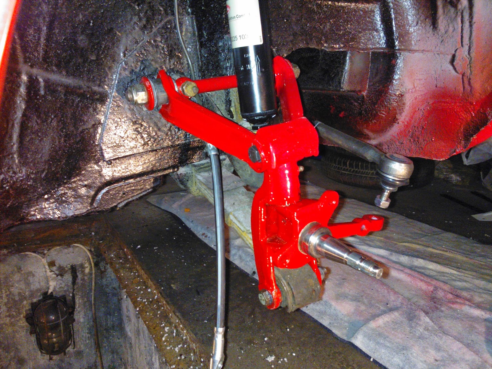
Most már csak rajtam múlik, mikor áll lábra ismét János. Tegnap megkaptam az összerakott első féltengelyeket, a kengyellel, új csapszegekkel. Kicsit ütött-kopott lett a szépen lefestett felület, ahogy a dolgok a helyükre kerültek benne, de egy gyors maszkolás és javító fújásoknak hála 1 óra alatt ismét szépen pompáztak. Hagytam hogy félig megszáradjanak, és két órával később óvatosan be is szereltem.

...és ilyen lett.
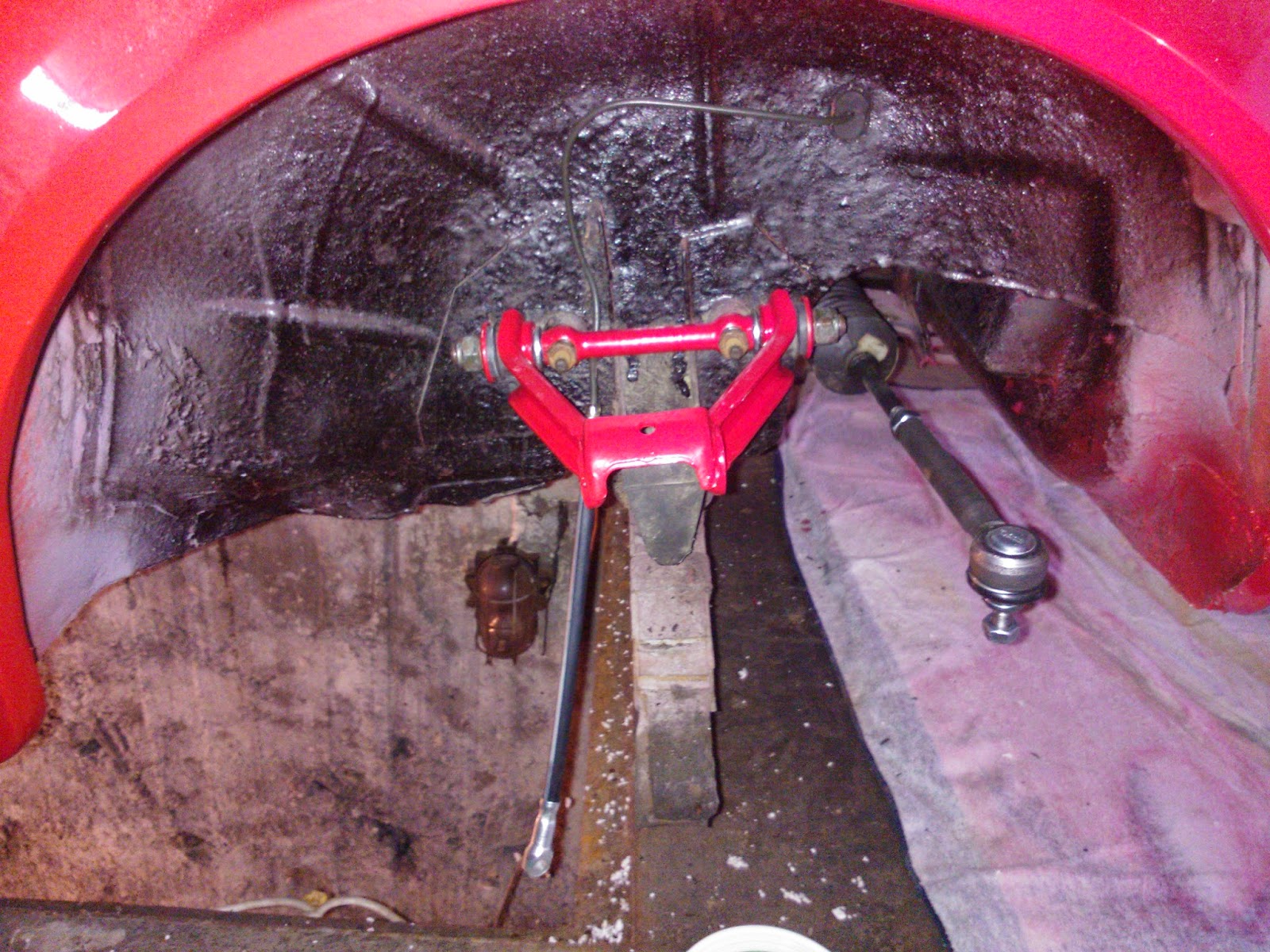
Előtte, a múlt hétvégén hasonlóan javítófújkálással megpermetezett lengőkarokat raktam a helyükre, miután összeszereltem őket. Ott is kapott ugyanis még egy kicsit, ahogy a szemben lévő szilenteket a helyükre kalapáltam (sajnos ezeket már nem sikerült préselni, ahogy az elsőt). Az is nagyjából utána a karosszériához fogva száradt ki rendesen. De ahhoz hogy ez meg tudjam tenni, egy-két csavart, alátétet is be kellett szereznem; nagy megelégedésemre megtaláltam a Szögkert - amit csak ajánlani tudok-, ahol még zéger gyűrűt is katam végre a kuplung pedál bowden rögzítéséhez, réz szigetelő alátéteket a fő fékmunkahenger csavarjaihoz, 10.9-es csavarokat a kengyel és lengőkar összekötéséhez, illetve a régóta szívató M12x1.5-ös anyákat.


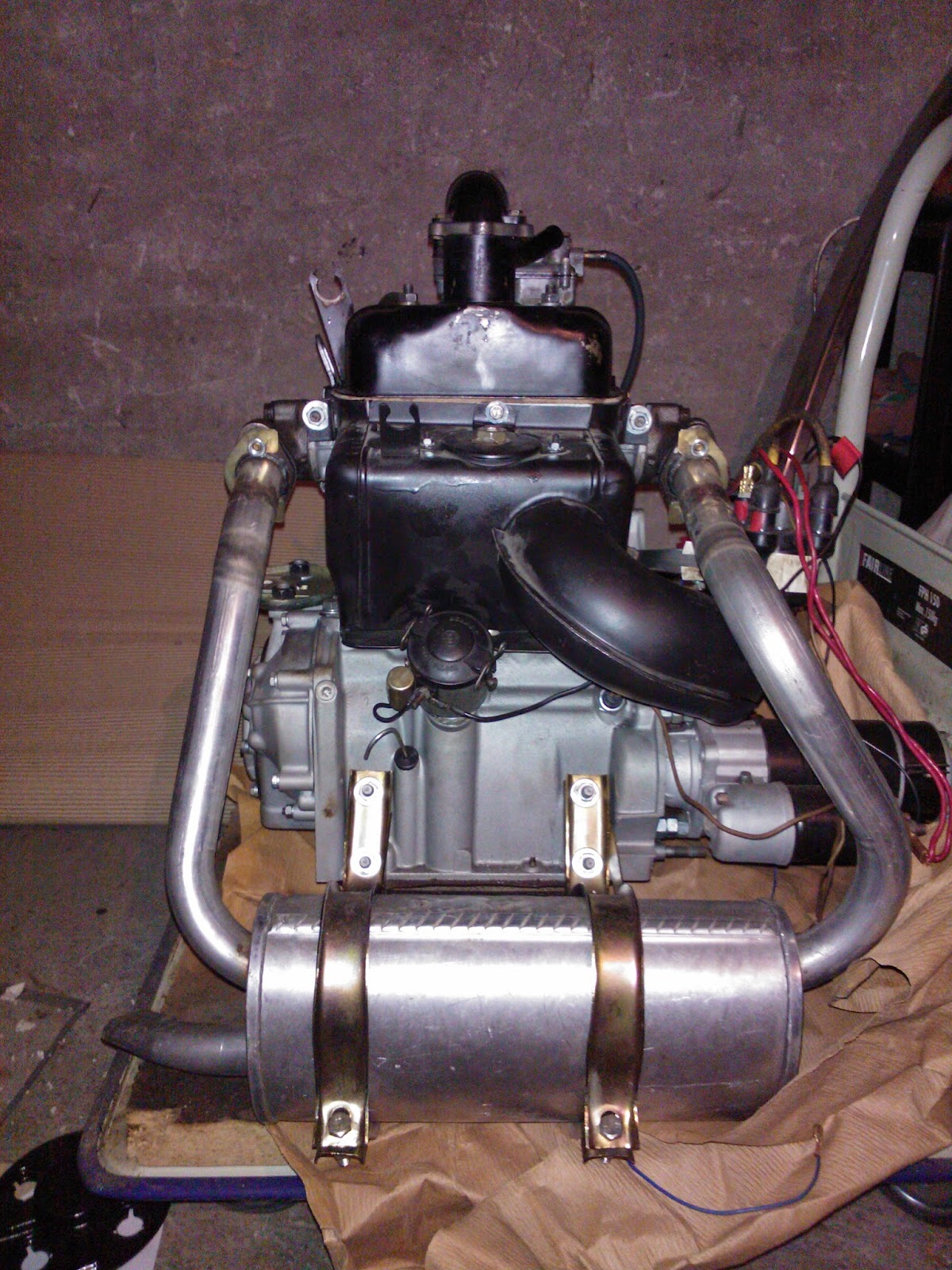
Elkészült a motorblokk üveggyöngyözése is múlt péntekre, így azt is vittem utána a szerelőmnek, a közben beszerzett, új motoralkatrészekkel. Ideiglenesen a régi szelepfedelet rátettük, hogy a szelepemelőket, rugókat, stb. védje. Így az is szép fémszínű lett kívülről, amit hétvégén szintén lefújtam, de ezt már fekete hőállóval.
Belülről a szinter még tartott rajta, így azzal külön nem foglalkoztam. Tartaléknak jó lesz, most már nem fog tovább romlani az állapota, mondhatni újszerű lett.

A kárpitokat is előbányásztam, és elvittem a kedvenc autómosómba, hogy tisztítsák ki rendesen. Az ajtókárpitoknak, meg a hátsó kerékjárati ív feletti műanyagnak jómagam estem neki: egyik oldalról benzin, majd mindkét oldalról szappanos víz (inkább Ultradermes, a szerk.).
A kárpitok még mindig nem száradtak meg, mert különben hívtak volna, de az ajtót már legalább készre tudtam szerelni. A jobb oldalit. Mivel kiderült, hogy a bal oldalihoz hiányzik (törött) a kilincs alátét, illetve az ablakemelő alátét. hmm...

A szellőző rendszert is körbeszigeteltem, a boltban kapható ablakszigetelővel. Így már biztosan nem sok helyen fog szelelni a váltórudazat alagút, amíg előre nem ér a meleglevegő! :)
A motor oldalsó levegőbeszívójára pedig kísérlet képpen felpattintottam 2 réteg gézt: elvileg nem fogja nagyon akadályolzni a levegő áramlását, viszont a nagyobb méretű koszok/pókok motorba/ventillátorba jutását megakadályozza, így tiszta maradhat a motor. Annó ugyanis amikor szétszedtem, a blokkon kisméretű faleveleket, nyárfa termést, és hasonlókat találtam (a rengeteg pókhálón, és poron túl persze, ami mind az olajba beleragadtak, és odaégtek).

Tegnap már csak az első fékek összerakása és beállítása lett volna, de kiderült, hogy a régi fékmunkahengerek úgy beálltak, mint a szög! Mozdítani sem lehet a dugattyúkat, csupa rozsda az egész. Ígyhát ide teljesen újakat fogok tenni, remélem báró-kernél van raktáron.

Ezen kívül persze még volt egy csomó apróság, mint pl.: szétszedtem, megpucoltam, és összerktam a korábban beszerzett króm visszapillantót, és felszereltem. Egy gumibelsőből vágtam neki alátétet, hogy a karosszériát ne birizgálja. Azt hiszem, nem tökéletes azért a dolog, mivel könnyen körbe tud fordulni sajnos.
A bemart profilú tartó rúd aláján a gömbhéj ellenlemez körbemarta a tengelyt. Ezzel nem tudom még mit fogok tudni kezdeni, mert látszólag a karral egybe van öntve.

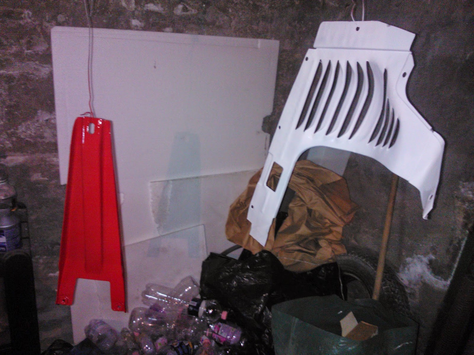
A motorhoz tartozó egy-két elemet is lefújtam, mint pl a légterelő lemezt a csiga alá, illetve a váltót eltakaró pajzsot, készülve arra, hogy megérkezik végre valamikor mindkettő.

A kerekeket is újra elővettem, és nekiálltam pucolni őket, kettős céllal: a fényező elég trehányul takarta le, és a gumin is, illetve a felnin is a festék köd kicsapódott.
Sima suvickolással nem jött le, így legalább a külsejét újra kell fújnom majd. A gumin a feliratokat pedig fehér gumifestékkel ki fogom emelni.